

pf cosθ= Voltage Drop V ( ) d ... Note: Motor hp rating relates to motor mechanical output. To determine motor input kVA requirements, the motor efficiency and power factor must be accounted for. In general, for preliminary or rough load calculations, assume: 1 kVA of electrical input power for 1 hp of motor. Example 9C1 Motors Condition: A motor control center with a total connected ...

Power Factor. In AC circuits, the power factor is the ratio of the real power that is used to do work and the apparent power that is supplied to the circuit. The power factor can get values in the range from 0 to 1. When all the power is reactive power with no real power (usually inductive load) .

b = voltage/connection c = phase d = wire e = pf current transformer with shorting terminal block a = quantity b = ratio variable frequency drive with features as shown a = input contactor b = output contactor c = bypass starter d = input circuit breaker b = fuse rating b = type, refer to disconnect schedule fused disconnect switch disconnect switch low voltage circuit breaker .
• ANSI, safety requirements 230 kV and below 833/958 through 8,333/10,417 KVA, singlephase, and 750/862 through 60,000/80,000/100,000 KVA, threephase without load tap changing; and 3,750/4,687 through 60,000/80,000/100,000 KVA with load tap changing • (ANSI) IEEE, standard test code for liquidimmersed distribution, power and regulating transformers and ...
Power factor (PF) is defined as the ratio of true power in watts (W) to apparent power volt–amperes (VA). A pure resistive load has a PF of 1. But in active loads, such as lightemitting diodes (LED) drivers, the mains supply current passes through a bridge rectifier and then the DC voltage is smoothed using a largeelectrolytic capacitor. As the capacitor only charges during the peaks in ...
Vfd panels in Kochi, Vfd panels in Thrissur, Vfd panels n Kollam, VFD panels in Kerala, Vfd in Thiruvananthapuram, Vfd in Idukki, Vfd in Kasargod, Vfd in Kottayam, VFD in Kollam, Vfd in Palakkad, Vfd in Alappuzha, VFD in Thrissur, VFD in Cochin, Best vfd suppliers in ernakulam, Variable Frequency Drive in kerala, Vfd panel in Kannur, Vfd panel in Palakkad, Vfd panel in .

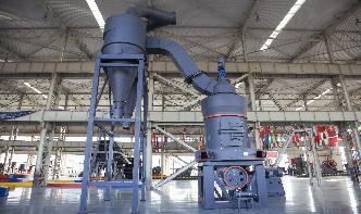
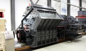
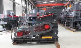
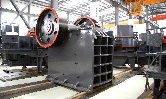
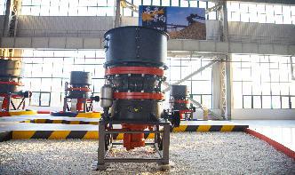
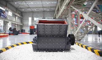
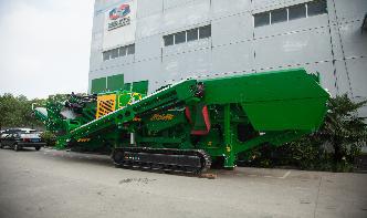
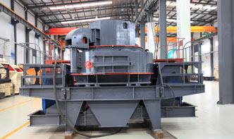
Pf 1315 Crusher Voltage Requirements Find Complete Details about 160 To 220 Tph Pf 1315 Impact Crusher,Pf Impact Crusher,Impact ... PF1210 impact crusher with reliable quality by Zhongde in Luoyang ...get price. Energysaving Pf1315 Impact Crusher. impact crusher pf 1315. impact crusher pf series and pfv series impact crusher .. it can operate smoothly with the advantages of energy .
Determine the phase current I in amps (A) by dividing the power P in watts (W) by 3 times the power factor PF times the line to neutral RMS voltage VLN in volts (V): (The power factor is the ratio of the real power flowing to the load to the apparent power in the circuit. Power factor values can range from 0 to 1. Line to neutral voltage is the voltage measured between any line and the ...
requirement up to lag to lead at the point of interconnection [1]. For solar PV, it is expected that similar interconnection requirements for power factor range and lowvoltage ride through will be formulated in the near future. Inverters used for solar PV and wind plants can provide reactive capability at partial output, but any inverter ...
•Voltage, VAR, PF control •PF requirements primarily met by WTG reactive capability, but augmented by mechanically switched shunt devices if necessary •Combined plant response eliminates need for SVC, STATCOM, or other expensive equipment •Integrated with substation SCADA . 6 / Wind Plant vs. Wind Turbine Reactive Capabilities Wind Plant pf capability wind turbine pf spec Reactive ...

Power Factor (PF) vs. Voltage Negative Power Factor Values Excitation Current vs. Voltage Temperature Correction Factors for PF Readings . 3 Power Factor Testing What is it ? • A form of AC testing that applies voltage and measures the leakage/loss current of electrical insulation. It is a type of insulation testing used to evaluate the integrity of electrical insulation. C HL Vs Insulation ...

The Dielectric Voltage Withstand Test page 2 The dielectric voltage withstand test is an integral part of the product safety evaluation of electrical and electronic devices, and provides manufacturers with important information regarding the quality and appropriateness of the chosen insulation system. The test involves placing an extrahigh voltage across the insulation barrier .
• pf overexcited (delivering 730 kVARs to the system) • pf underexcited (drawing 730 kVARs from system) Frequently provides +/ pf at POI The supervisory control will instruct individual machines to adjust their reactive power output in order to regulate system voltage; normally at the pointofinterconnection

30 mA (2500 pF). Under a no load condition, supply current stays relatively flat. Figure 7 shows a true RS232 appliion where one driver (TXD) is switching while the other two are driver (DTR and RTS) remain High (loaded) as shown in Figure 3. At 10 kHz, supply current reads 26 mA (2500 pF), under this real world RS232appliion ...

•Voltage, VAR, PF control •PF requirements primarily met by WTG reactive capability, but augmented by mechanically switched shunt devices if necessary •Combined plant response eliminates need for SVC, STATCOM, or other expensive equipment •Integrated with substation SCADA . 6 / Wind Plant vs. Wind Turbine Reactive Capabilities Wind Plant pf capability wind .

Output Low Voltage V OLA V Y = 0 V, I OL = 20 µA, see Figure 27 V Capacitance3 C A f = 1 MHz, EN = 0, see Figure 32 9 pF Leakage Current I LA, HiZ V A = 0 V/V CCA, EN = 0, see Figure 29 ±1 µA Y Side Input High Voltage 3 V IHY × V CCY V Input Low Voltage 3 V ILY × V CCY V Output High Voltage V OHY V A = V CCA, I
Copyright © 2023 CNMIning، Industry & Technology Group Co., Ltd. خريطة الموقع
